Computed Tomography (CT) has come a long way since its public inception in 1972. The rapid improvement of CT and the increasing capabilities of CT scans have definitely gone hand in hand. CT scans that used to take hours, now take seconds. This increase in capabilities has led to the use of CT scans more often and in more ways than ever before. The use of CT in the industrial nondestructive testing (NDT) field is one segment that has grown tremendously in the past few years.
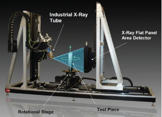
Industrial CT uses a series of 2D images taken at specific intervals around the entire sample. Any type of industrial CT system uses three principal components: an X-ray tube, an X-ray detector, and a rotational stage. Everything is enclosed in a radiation,
shielding steel/lead/steel cabinet that usually ranges between 4ft³ and 10ft³. This allows use of the system in a public environment without any additional safety concerns.
shielding steel/lead/steel cabinet that usually ranges between 4ft³ and 10ft³. This allows use of the system in a public environment without any additional safety concerns.
Micro computed tomography (microCT) is primarily the same as standard CT except it uses a microfocus tube instead of a traditional tube. A microCT scan yields resolutions in microns because the focal spot of a microfocus tube is only a few microns in size. For comparison, microCT resolution is about 100 times better than the best CAT scan in the medical field.
High quality industrial X-ray detectors used for CT are typically a new generation Amorphous Silicon Flat Panel Area Detector, offering very high sensitivity, resolution, and bit depth. The resulting 2D X-ray images are very clear and the contrast is unparalleled.
Acquisition
A modern high-end CT scan consists of taking several 2D X-ray images around the object, preferably covering 360°. CT systems typically acquire between 360 images (one image every degree) and 3,600 images (one image every 0.1°), depending on the final desired resolution. Each image is between 3 megapixels to 10 megapixels, and is also averaged and filtered to reduce noise. The 2D digital images taken during this step are saved directly into a single folder that will be used in the next step of the CT process.
Reconstruction,Visualization
Once the acquisition process of the CT scan is completed, CT calibration and CT reconstruction algorithms are used to reconstruct the 3D CT volume. These 3D images are made of Voxels (3D pixels), and, with the use of visualization software, the 3D volume can be manipulated in real time. Because of this, it is possible to slice through anywhere inside the object, inspect and look for defects, take accurate measurements, reconstruct a surface model, and more.
Industrial CT technology is improving very quickly. While a few single CT slices could take hours to generate years ago, it is now possible to reconstruct complete 3D models with billions of voxels in just seconds. This opens the door for numerous new applications like 3D in-line automatic and defect recognition, 3D reverse engineering, rapid prototyping, and 3D metrology. In that regard, industrial CT has become a very competitive technology for 3D scanning.
The principal benefit of using 3D CT for scanning or digitization is that a complete model with both external and internal surfaces of an object is obtained without destroying it. Moreover, CT works with any surface, shape, color, or material (up to a certain density and/or thickness penetrable with X-rays). Generally, a modern start-to-finish CT scan can be as fast as two seconds or take longer than an hour, depending on the resolution requirements and size and/or density of the object. Overall, the resolution is excellent both internally and externally, which, in turn, can fulfill virtually any designer’s needs.
in real time 3D and it is also possible to slice through in any direction for internal inspection.

Computed Tomography
CT has proven to be an outstanding tool for many industries. Industries such as medical device, pharmaceutical, aerospace, electronics, and many more have made CT a part of everyday life. The demand for CT continues to be tremendous; largely due its versatility and capabilities to do what other technologies cannot. CT scans nondestructively provide excellent resolution internally and externally, which then allows for measurement on surfaces both inside and outside an object. In addition, due to the penetration of X-rays, CT scans are unaffected by certain object characteristics such as dark, reflective or transparent surfaces, and/or shaded zones on the item that can cause difficulty with other 3D scanning methods. Furthermore, 3D CT reconstruction models can be directly compared to CAD models and/or other CT models in order to display differences or commonalities in measurements, densities, voids, and more.
The reconstruction process consists of complex algorithms that transform the stack of 2D X-ray images to a 3D voxel volume model. This process uses a GPU (graphics processing unit) based software which utilizes the NVIDIA graphic card capabilities. NVIDIA’s graphic card employs hundreds of computation cores. This massive number of cores accelerates the process and increases the speed of 3D CT reconstruction by a factor of up to 50x. Developed with a CUDA interface, and the latest technology in graphic cards, this proprietary North Star Imaging software now makes it possible to perform very fast CT reconstruction, which, in turn, boosts the number of achievable scans. Due to the high speed capabilities, inline CT scanning for 100% quality inspection or 3D metrology control is now attainable.
Many options are possible with a 3D CT reconstruction volume model. For basic 2D measurements, the slice window is generated from the cutting plane in the 3D volume. From there a length and diameter angle can be applied on the single image. The main benefit, of course, is that any feature, part, or even defect inside a structure or an assembly can now be measured without destroying it.
The 3D CT reconstruction, which is made of several million or billion voxels, can also be transformed to a surface model. The resolution of the 3D model depends on the number of voxels generated from CT reconstruction. The operator chooses a threshold value of radiodensity, which is then set using edge detection image processing algorithms. From this, a 3D model can be constructed and displayed on screen. Multiple models can be constructed from various different radiodensity thresholds, therefore allowing different colors to represent each component of an assembly. Typically, models are composed of thousands of polygons and up to 50 million polygons.
With the generated polygon mesh surface model, many different applications become available to the user. The output format (points cloud, STL, WRL) is compatible with most CAD software for reverse engineering applications, rapid prototyping machines for modeling, and finite element analysis software for simulations.
In most cases, the polygon mesh generated by the CT system can be used in the above applications without modification and typically, the resolution is higher than needed. However, in order to modify or take measurements of the CT surface model with a CAD software, the CT model needs to be processed to make it editable. New generation modeling software (e.g. Geomagic, Rapidform, and Polyworks) propose semi-automatic tools to transform the polygon mesh to NURBS surfaces and parametric CAD models. User intervention is still necessary for manual operation in transforming the scanning surface to real solid CAD.
3D CT Versus CAD Model
Dimensional analysis is one key application available for model comparison. Since CT and especially microCT provides very accurate dimensions on surfaces, the technology is often used for metrology studies. Measurements can be done either directly on the surface using any CAD or metrology software, or it can automatically compare the CT model with the CAD model, or even the CT model with another CT model.
Geomagic Qualify is very efficient software for this type of application. It has the capability to perform a 3D and/or 2D comparison in very few steps, as well as to export metrology reports containing tons of information. Once again, the data includes both internal and external surface information.
Due to the proprietary nature of many aerospace components, a CAD to CT comparison is not available for display. As a replacement, for example, a dimensional comparison between a Solidworks CAD model of a casting provided by Twin Cities Die Casting, and the CT surface reconstruction created by NSI was done by the customer.
In order to do this comparison, the two models needed to be aligned. Different alignment tools are available, ranging from very fast and automatic best fit, to manual alignment. Once the two models are aligned, a simple 3D comparison option automatically creates a colored view showing all the dimensional differences between the two models.
In the example, all the dimensional differences between the Solidworks model and the actual CT surface (polygon mesh) are represented by colors. Tolerances between -0.300mm and +0.300mm are shown in green. Yellow denotes the areas where the CT scan measurements are larger than the original CAD model, and blue indicates smaller measurements. It is possible to change tolerance values and the color code to cater to a specific project or preferences. Numerical values are an available option as well.
Rapid Growth
Overall, 3D CT is now accessible for most industries as a viable tool; user-friendly interfaces, increased scan speeds, and decreasing prices have all attributed to the rapid growth of this technology in the marketplace. Having very accurate internal dimensions without destroying the item, along with the ability to compare to a reference model is unique to CT. There are no shaded zones, it works with all kinds of shapes and surfaces, there is no post-processing work needed, and the resolution is excellent. Above all, the greatest benefit is the ability to obtain, nondestructively, the internal structure of the object, and CT is the only technology capable of achieving such performance.
Source: North Star Imaging Inc. (Jullen Noel )